Thursday, August 31, 2023
Introduction
Most AC-DC power supplies have an internal EMI filter and to meet the CE and UKCA mark requirements, they must be also tested to the Electromagnetic Compatibility (EMC) requirements to an applicable standard like EN 55032 (Electromagnetic Compatibility of Multimedia Equipment) or EN 55011 (industrial environments).
There are often situations where additional system filtering is required to comply with these regulations. Power supplies are tested for the manufacturer by certified laboratories in optimum, repeatable conditions. Input and output cabling is well separated, and resistors used to load the product under test.
With system space constraints the layout of wiring may not be ideal, or if the power supply is being used to power fast-switching microprocessors, additional electrical noise could be generated. Some power supplies, particularly open frame models, may require additional filtering or shielding. In this case an external EMI filter may be needed.
Selecting a filter
The first step is to determine the electrical requirements. Let us consider an application using TDK-Lambda’s 4,000W TPS4000-24 (see Figure 1) power supply, and that the system will be operated on a three-phase AC input of 400 to 480Vac.
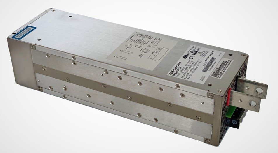
Figure 1: TPS4000-24 power supply
Input voltage
The first parameter to consider is the input voltage. Common AC input filter voltage ratings are single phase 250Vac or three phase 500Vac. As a note a 250Vac filter can be used with 115Vac inputs. For our TPS power supply we would need a 500Vac rated three phase filter.
Current rating
Next, we need to determine the filter’s current rating. Measuring the input current of the power supply would be one method, but a more accurate way is to look at the power supply’s rating label or a safety certificate for the maximum current. From the UL report (Figure 2) we can see that under full load, nominal input we would need a system filter rated at 8A as a minimum. If there are additional power supplies and other AC loads in the system, then the filter’s required rating would need to be increased accordingly.
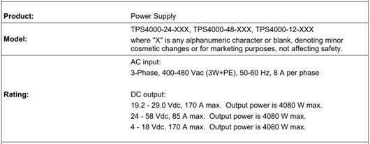
Figure 2: Extract from the TPS4000 safety report
It is not recommended to run any electrical product, even a filter, at 100% load continuously. Typically, a 25% derating should be applied, so we would consider as a bare minimum a 10A rated filter. Operating a filter above its rated value, even for short periods, can cause the internal inductors to saturate and become ineffective at reducing conducted EMI. For the example in this blog, we are going to use the TDK-Lambda 500Vac, 20A rated RTMN5020 filter.
Ambient temperature
The best location for an EMI filter in a system is close where the input wiring enters, which is often at the bottom of an enclosure. Measure the ambient temperature in this location and review the filter’s derating curve. It shows that even in a 70oC ambient our 20A filter is suitable.
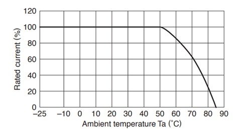
Figure 3: RTMN derating curve
Immunity
As mentioned in an earlier blog, the ability of equipment to withstand external electromagnetic signals is also covered under immunity standards and required when applying the CE/UKCA marks to a product. EMC filters can attenuate (reduce) high voltage pulses that may occur from electrical storms, relay switching or induction motors in an industrial environment.
The TDK-Lambda R series of filters include models that utilize amorphous cores to reduce impulsive noise spikes, rather than metal oxide varistors (MOVs) or voltage dependent resistors (VDRs). MOVs clamp spikes, but degrade over time following multiple line surges. Amorphous cores are made from very thin (μm) ferromagnetic amorphous metal strips wound to form a doughnut shaped core, and do not degrade.
In our example, if the power supply may be subjected to high voltage pulses, the RTMN filter series should definitely be considered. Figure 4 shows the filter’s attenuation of high voltage pulses.
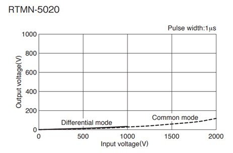
Figure 4: RTMN filter pulse attenuation
Using the Attenuation vs Frequency Characteristic plots
A power supply manufacturer should be able to provide the conducted EMI test results for their product, as shown in Figure 5.
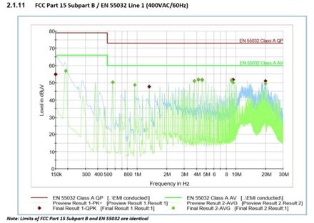
Figure 5: TPS4000-24 conducted EMI test results
These plots will indicate frequencies that may require additional filtering. Figure 6 shows our filter’s attenuation plot, indicating that it is suitable for giving us additional margin. As the filter has two stages, its performance is very good.
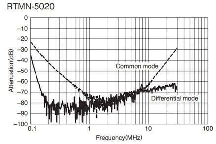
Figure 6: RTMN-5020 attenuation vs. frequency characteristic
For medical applications, earth leakage current can be very important. Many filters have a low leakage version, but note, this can impact the filter’s attenuation performance.
EMI Testing
Constructing a fully compatible test chamber for both radiated and conducted EMI is very expensive ($1M+) and will occupy a great deal of space.
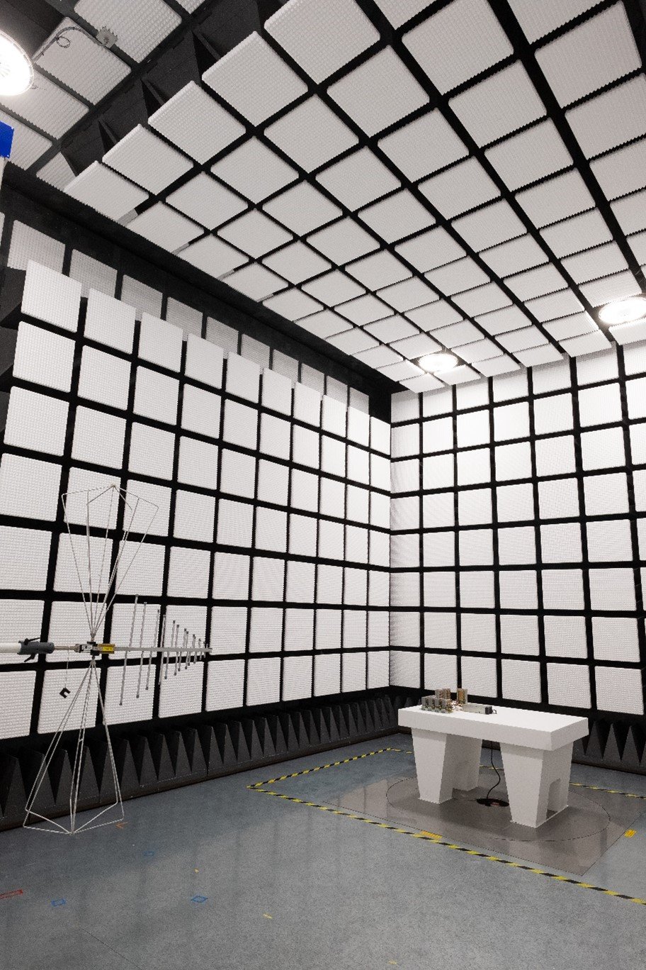
Figure 7: TDK-Lambda UK’s EMI test chamber
Many engineers rent a spectrum analyzer and a LISN (Line Impedance Stabilization Network) which creates a known impedance for the AC source. This enables tests to be performed to determine that there is a good probability it will pass when retested at a certified test location. This avoids expensive retesting.
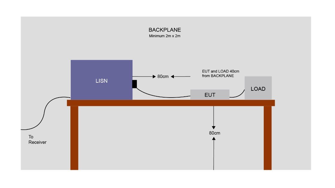
Figure 8: Typical conducted EMI test set-up
TDK-Lambda also suggests bringing a selection of different performance EMI filters. This avoids having to reschedule with the test house (at extra cost), and can also minimise the filter cost. TDK-Lambda Technical Support can also assist with your design and give advice on cable routing and noise suppression.
Power Guy