Monday, July 17, 2023
Introduction
Electronics has now become entrenched in everyday life, replacing many devices that would previously be described as “electrical” in nature. With technology, comes the need to reduce electrical noise and protect equipment against the effects of electrical noise. One solution to overcome this problem is the use of EMI/EMC filters.
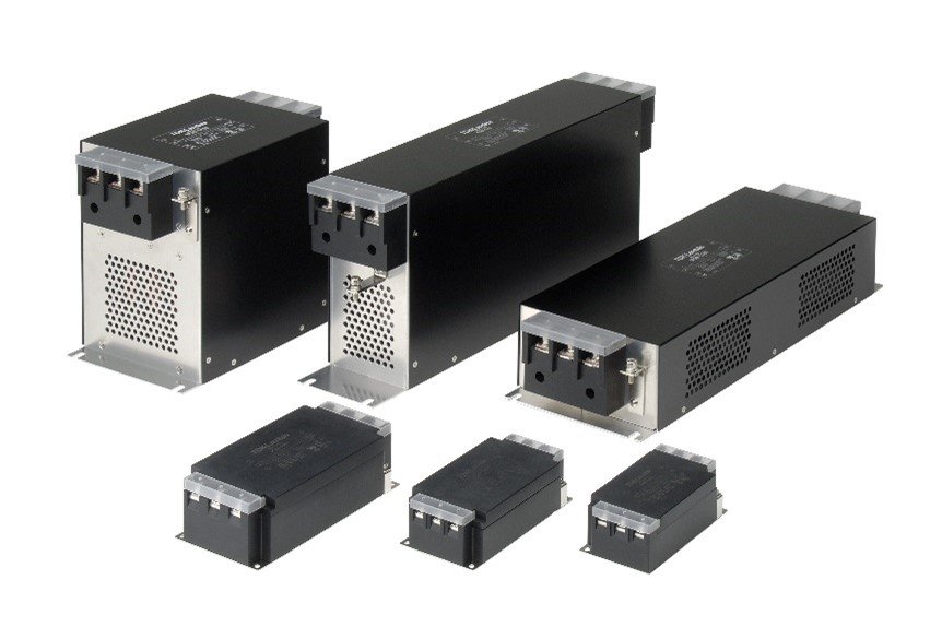
Figure 1: TDK-Lambda EMI/EMC Filters
Terms used
A quick web search will result in a number of terms and expressions to describe these filters. They include “noise filters”, “EMI filters” and “EMI/EMC” filters. To understand if a filter is suitable for an application, we first need to review the differences between EMI and EMC.
EMI and EMC Legislation
From a legislative viewpoint, EMI (ElectroMagnetic Interference) is the measurement and restriction, to defined limits, of unwanted conducted or radiated electrical noise from a source. Both the power supply and the equipment it is powering may be considered the “source”.
EMC (ElectroMagnetic Compatibility) is the ability of equipment to withstand, again to defined limits, a variety of external electromagnetic signals. Regulation of both the “source’s” emissions and the ability of the load to function under those emissions (and other potential external influences), guarantees the end product a defined level of performance.
Why is legislation required? If an LED light bulb in a residential application were to flicker or turn off briefly due to an AC voltage dip during an electrical storm, it would be unlikely to cause harm or serious injury. If that same storm were to impact the performance of life support equipment in a hospital, trackside railroad signalling or the radar system for an airport, serious harm could occur.
International standards for AC-DC and DC-DC power supplies
EN 55011, EN 55032 and EN 61000 are the most widely used standards, which cover emissions and immunity. For EMI, the less stringent Class A level is used for industrial applications and the more stringent Class B for medical and household applications. These in part refer to the standards of CISPR (International Special Committee on Radio Interference). Figure 2 shows levels for an AC-DC power supply over the 150kHz to 30MHz range required for EN 55011.
In the US, FCC Part 15 is used to regulate “unlicensed” radio frequency (RF) transmissions. MIL-STD-461 is the US military standard for subsystems.
In the European Union (EU) manufacturers of electronic equipment have to state their compliance by labelling their product with the CE Mark to the EU Directive 2004/108/EC. For the UK, the UKCA mark is applied. These marks refer to multiple standards according to the end application.
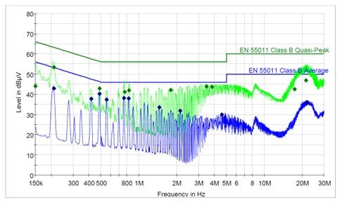
Figure 2: EN 55011-B conducted emissions plot and limits for an AC-DC power supply
Regulation of EMC immunity is usually defined by IEC 61000, which is a very broad set of standards. For the purpose of this blog, only the two sections applicable to a typical EMI/EMC filter used with an AC-DC power supply will be discussed.
EN 61000-4-4: Electrical fast transient/burst immunity testing – bursts of electrical noise are injected on the input lines to simulate inductive switching, relays, etc.
EN 61000-4-5: Surge immunity testing – single pulses are injected on the input lines to simulate lightning strikes and high energy switching.
To address the impact of harm, both of the above include different immunity test voltages (ranging from 500V to 4,000V peak) and different performance criteria (A through D). With criteria A the product will continue to operate as normal during the test, B states an automatic recovery after the test, C requires user intervention to restart the product and D is a loss of function that is not recoverable. If a product was being used in a critical application, then criteria A would be used of course.
How does an input EMI filter work?
EMI is generated from the switching of electrical currents and from a variety of sources including electronic power supplies. Power supplies convert an input voltage into regulated and isolated (in most cases) DC voltages to run a host of electronic products. That conversion is performed at high frequencies ranging from several thousand times a second to more than a million and generates electrical noise.
A simple external EMI filter for a power supply will consist of passive components, including capacitors and inductors, connected together to form L-C circuits. The inductor(s) allow DC or low frequency currents to pass through, while blocking the unwanted high frequency currents. The capacitors provide a low impedance path to divert the high frequency noise away from the input of the filter, either back into the power supply, or into the ground connection.
Figure 2 shows a simple single stage power supply filter
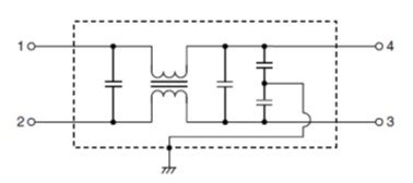
Figure 2: Single stage EMI filter
Why is an EMI filter needed?
One common question asked is “if the power supply meets the EMI/EMC standards, why do I need an external filter?”
Power supplies are tested for the manufacturer by certification laboratories in optimum, repeatable conditions. Input and output cabling is defined, and resistors are often used to simulate a load for the product.
Unfortunately, when installed in a system, space constraints may add noise through closely coupled cables, particularly if the input and output wiring are not sufficiently separated. System microprocessors, motors, transmitters and other devices can also generate additional noise. In this case an additional system EMI filter may be needed for the system to pass EMC testing.
In some cases, manufacturers will rely on external shielding around their power supply, which may not be mentioned in the EMI test report.
Another blog will cover how to select a filter and how EMI/EMC testing is performed.
Power Guy