TDK-Lambda Americas Blog
How to use power factor correction power modules (Part 2)
Tuesday, January 31, 2023
Part 1 of this blog is about why power factor is needed and the international standards governing harmonic current emissions. Part 2 will provide some information regarding how to use a power factor correction (PFC) module, in particular using the TDK-Lambda PF1500B-360 (Figure 1). It is advisable to read Part 1 of this blog if you have not already done so.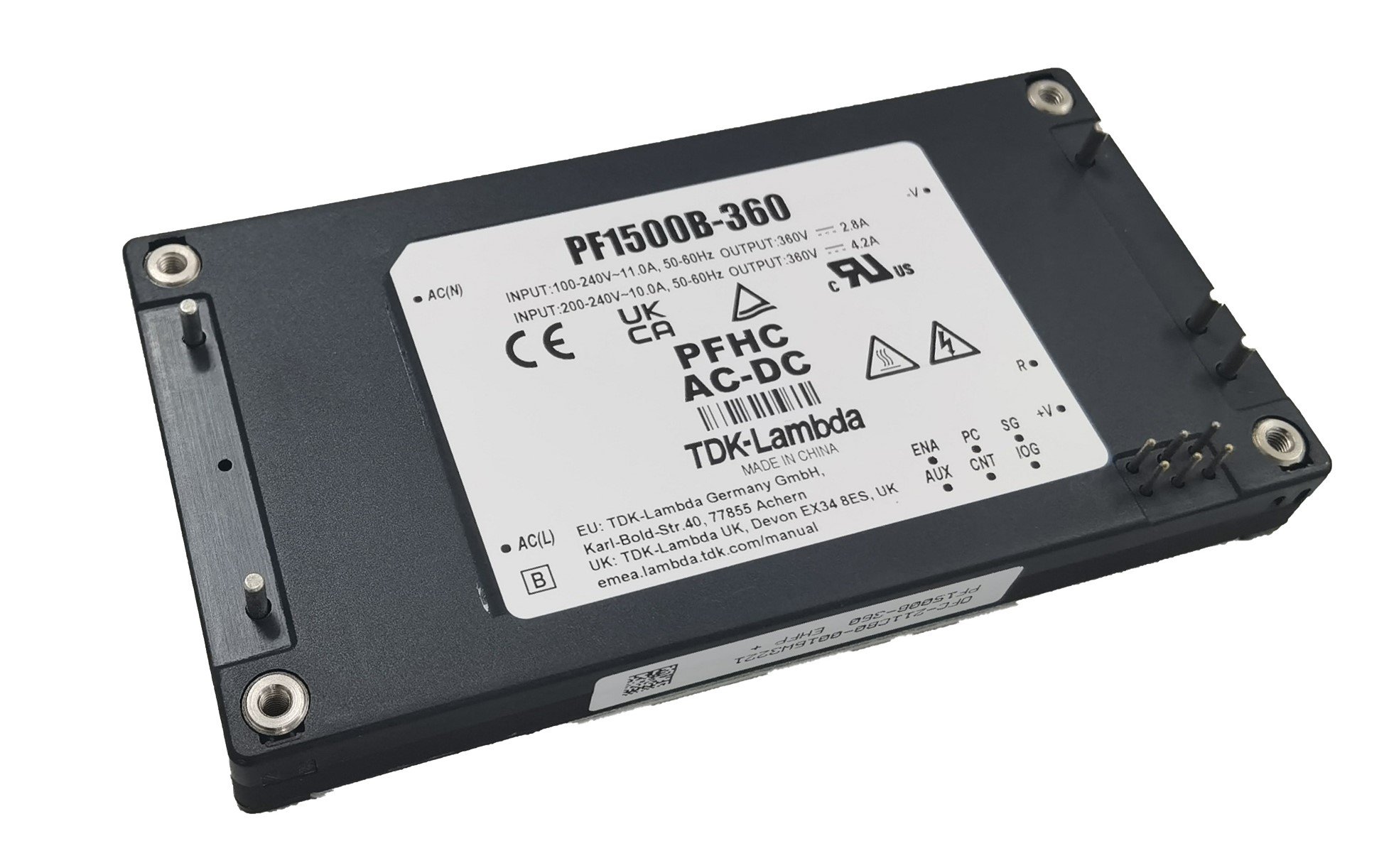
Figure 1: TDK-Lambda PF1500B-360
The TDK Product Center website has some good information on this module, including the evaluation, immunity and reliability data, as well as the specification and instruction manual. I have to admit, that as an Engineer (outside of work) I do tend to lean towards “if all else fails read the manual”. When working with power modules though, reading the manual is a very good idea. We have had some good conversations with designers needing help to solve problems that could have been averted if they had first read the manual.
This blog explains about why certain components are used and what they actually do.
Block diagram
First a high-level explanation of how the module works, using the block diagram (Figure 2).
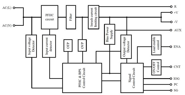
Figure 2: PF1500B-360 block diagram
The AC source feeds in to the PFHC (Power Factor Harmonic Correction) switching circuit (operating at a fixed frequency of 127kHz) which converts the AC into 360Vdc. The filter circuit consists of one or two capacitors used to dampen noise spikes from the module and provide a low impedance source for ripple currents from the converter.
In parallel with the filter section is the inrush current limiting circuit and bulk energy storage capacitors. The initial bulk capacitor charge current is minimized to avoid damage to the input fuse, relay or nuisance tripping of a circuit breaker.
The main controller manages the operation and protection of the PFHC circuitry and bias power supply (BPS). This includes the overtemperature protection (OTP) and overvoltage protection (OVP).
The signal control circuit manages the remote on/off (CNT), the inverter good (IOG), parallel control (PC) and the enable (ENA) circuit to activate the PF1500B-360’s load when the output reaches 350Vdc.
PF1500B external components (Figure 3)
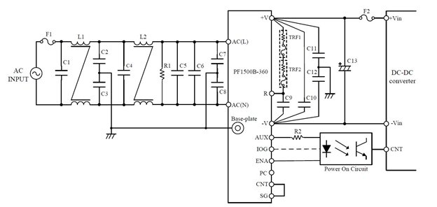
Figure 3: External components used on the PF1500B
Input filter section (Figure 4)

Figure 4: Input filter section
It is necessary to ensure your end product meets the applicable EMC standards. This is governed by many countries and required for the application of the CE and UKCA marks. In the PF1500B evaluation report, the product was tested to EN 55032 which has the same levels as EN 55011. An external two-stage filter circuit (shown in figure 4) is suggested for the best performance.
Fuse F1 should be a safety certified 20A 250V rated fast-blow type. If modules are being used in parallel, each module should have its own fuse.
Capacitors C1, C4, C5 and C6 are connected across Line and Neutral and avoid electrical noise from travelling back into the AC source, keeping it localized in the power supply. These must be safety certified “X” film capacitors with a recommended 275Vac rating, and a value of 1µF or more. Position C5 and C6 as close to the AC(L) and AC(N) of the power module for maximum effectiveness.
Capacitors C2, C3, C7 and C8 also avoid electrical noise from going back into the AC source. This time the noise current is bypassed into the earth ground. As they are connected between L/N and ground, these must be safety certified “Y” capacitors with a recommended rating of 2200pF. C7 and C8 should be positioned close to the AC input of the module.
The common mode inductors L1 and L2 should have a minimum value of 4.5mH and 1.3mH respectively and have a current rating of 12A (if operated at 100-240Vac) or 9A (if operated at high line 170 to 265Vac).
Bleed resistor R1 discharges the X capacitors to avoid an electric shock when unplugging the AC power cord. The value should be 470kΩ. Now that IEC 62368-1 is in force, the resistor should comply with the standard, or two resistors should be used in parallel to pass the “single fault clause”.
Output filter and inrush current limiting (Figure 5)
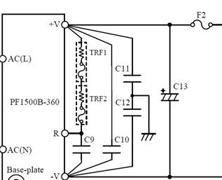
Figure 5: Output filter and inrush current limiting
C11 and C12 filter any high frequency noise on the output of the module. It is advisable to use the same capacitors as C2, C3, C7 and C8. Position them close to the DC output of the module. The further away they are, from the output, the less effective they become.
C9 and C10 are Polyester Film 2.2µF film capacitors with a minimum rating of 3A RMS, 450Vdc as the module output is 360Vdc.
TRF1 and TRF2 are the inrush limiting resistors which also have internal thermal fuses. These types of resistors are recommended for safety protection. Using a non-fused wire wound resistor can cause damage if a short occurs within the power module.C9 is in series with the two resistors and when charged, the converter will start up, bypassing the inrush resistors to save energy.
C13 is the bulk energy storage electrolytic capacitor, providing sufficient hold-up charge in the event of a short interruption to the AC supply. This should be rated at 450Vdc and be between 470µF and 2,700µF with a low impedance (Nippon Chemi-con KXN Series or equivalent). Using a smaller amount of capacitance will affect the output hold time, dynamic line response and dynamic load response characteristics.
Fuse F2 is in series with the positive output to protect the load from possible damage and should be a 500Vdc, 6.3A rated fast blow type.
The printed circuit board design should be completed with input from the person who handles your certification with the regulatory safety bodies (UL, CSA, etc). Minimum spacings (creepage and clearance) are required between high voltage copper traces and between primary and earth.
A multiple layer circuit board is recommended with a ground plane to reduce EMI. The higher current carrying traces should be thick and positioned close together to reduce the impedance for the capacitor switching currents. The thickness and mounting hardware of the circuit board should reflect the weight of the components.
Calculations for the components mentioned above can be found in the instruction manual. Do not hesitate to call or email TDK-Lambda Americas Technical Support or your local sales office. https://www.us.lambda.tdk.com/contact/