TDK-Lambda Americas Blog
Power Factor Correction (Part 1)
Monday, December 19, 2022
This will be a blog in two parts, one discussing aspects of power factor correction (PFC) and one about using a PFC module.
Why is active power factor correction required?
Unlike a resistive load running from an AC source, most switch-mode power supplies will not draw a sinusoidal input current without power factor correction circuitry placed between the input bridge rectifiers and the energy storage DC bulk capacitor(s). See Figure 1.
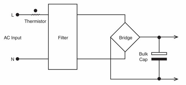
Figure 1: Simplified schematic without power factor correction
Without power factor correction, the input current will be drawn for a short period as the AC voltage reaches its peak (Figure 2). This produces high RMS currents, which can overheat wiring, potentially causing fires, and reduce the amount of power that can be drawn from an electrical socket. An earlier 2008 blog can provide more detailed information on this.
This type of power supply may have a power factor as low as 0.4, compared to a value of 0.95 or higher for one with active power factor correction.
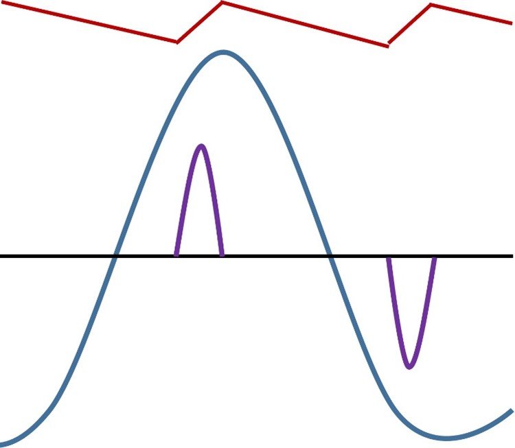
Figure 2: Bulk capacitor voltage (red), input voltage (blue) and input current (purple)
It may be worth noting at this point that improving reactive power factor correction is a completely different technique. This is used with inductive AC motors to avoid a phase lag between the voltage and current. Adding AC rated capacitors across the load reduces the phase lag and improves the reactive power factor. Electricity providers will often penalize facilities who have a poor reactive power factor.
As shown by Figure 3, one method of improving a power supply’s power factor is to add a boost converter circuit before the bulk capacitor C1.
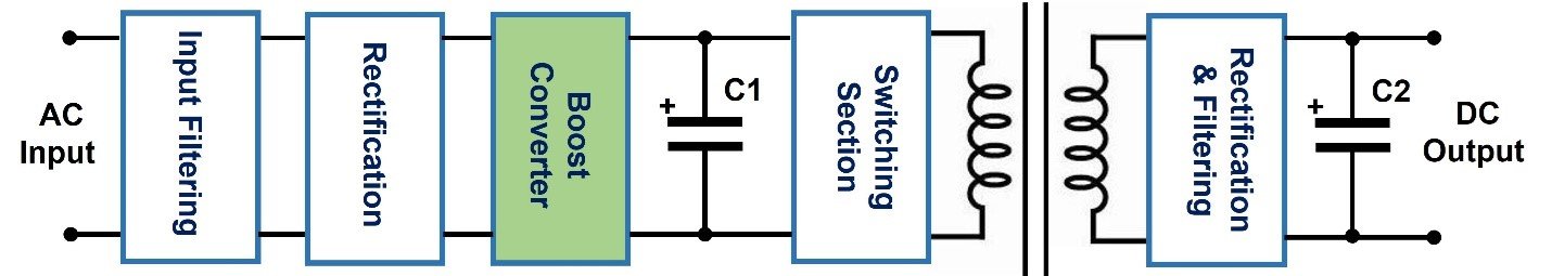
Figure 3: Block diagram of a power supply with power factor correction
The boost converter measures the input current, compares it to the input voltage and adjusts the boost voltage accordingly. This produces a sinusoidal current waveform with a lower RMS value in phase with the voltage waveform (Figure 4).
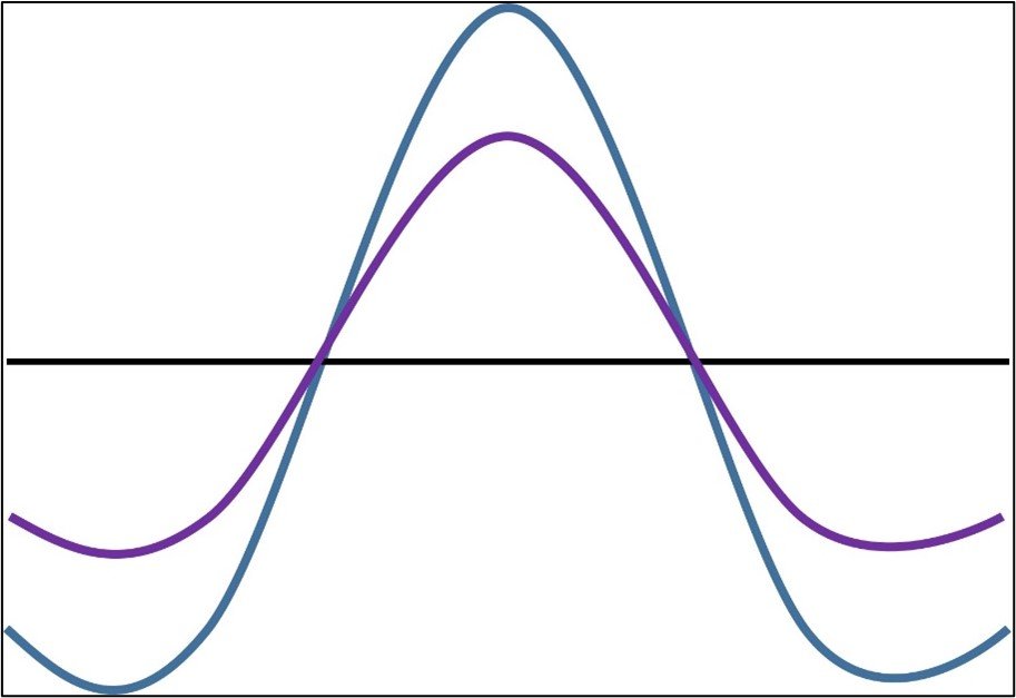
Figure 4: input voltage (blue) and input current (purple)
International standards and regulation
The IEC 61000 family of EMC (Electromagnetic compatibility) standards addresses a large number of topics. These are called out in other high-level standards like EN 55032 and EN 55011. IEC/EN 61000-3-2 is one of them, regulating the limits for harmonic current emissions with a 220Vac input and input currents of ≤ 16 A per phase. It is also a requirement for placing a CE and UKCA mark on a product under the EU EMC Directive 2014/30/EU and UK Electromagnetic Compatibility Regulations 2016.
What have harmonics got to do with power factor correction? A non-sinusoidal waveform is made up of a fundamental sinusoidal frequency and a number of harmonic frequencies. Power factor correction circuitry will not provide a perfect sinusoidal input current waveform and therefore will generate additional harmonic currents.
Rather than basing the IEC standard on the measured power factor, it addresses the amount of current allowed at a number of frequencies. These are either numeric or percentage limits. There are four classes in the standard and I will list them with their most popular application. Class A – appliances, Class B – portable tools, Class C – lighting equipment and Class D – PCs and monitors, radio or TV receivers.
There are a number of excellent power quality analyzers and meters on the market, so I will not list all the current limitations. A typical plot of the harmonic current values is shown in Figure 5.
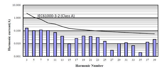
Figure 5: Measured harmonic currents and limits for the TDK-Lambda PF1500B module
Not all power supplies will need power factor correction circuitry. Equipment rated less than 75W may pass or be exempt.
Power Factor Correction modules
Power modules, like TDK-Lambda’s PF1500B-360, (Figure 6) accept a wide range AC input and provide regulated, non-isolated 360Vdc outputs. These can be used in conjunction with 200 to 425Vdc isolated DC-DC converters or equipment requiring a high voltage DC source. They have the ability to be conduction or convection cooled through their aluminum baseplate and utilized in sealed enclosures for harsh or environments with airborne contaminants. A low height of 12.7mm enables them to operate in applications that may be subjected to shock and vibration.
Figure 6: TDK-Lambda PFC power module
As noted earlier, I will cover applications for these type of power supplies in part 2 of this blog with some basic “how to use” information.
Power Guy