Tuesday, September 9, 2025
The landscape of modern electronics is one of ever-increasing complexity. Product engineers are tasked with powering a growing number of discrete loads, each with its own unique voltage and current characteristics, all while facing relentless pressure to improve efficiency, reliability, and cost-effectiveness. The selection of a DC-DC power converter is a foundational design choice of whether to employ an isolated or non-isolated converter, with consequences that permeate through the entire system design, impacting everything from safety and noise performance to size, weight, and cost.
This article offers the differences between isolated and non-isolated DC-DC converters, the implications of selecting one over the other, and serves as a comprehensive guide for navigating this critical decision.
The Fundamentals of Isolation
It is essential to understand the fundamental difference between these two converter classes. The distinction lies in the concept of galvanic isolation, the principle of physically and electrically separating two parts of a circuit.
An isolated DC-DC converter achieves this separation by using a transformer to transfer power between its input and output stages. There is no direct electrical conduction path between the two sides; instead, energy is transferred across an insulation barrier via a magnetic field. This creates two galvanically separate circuits, each with its own electrical reference (commonly referred to as ground or common). This barrier is the key to an isolated converter's most valuable features: safety, electrical noise mitigation, and design flexibility.
A non-isolated DC-DC converter, by contrast, has a direct electrical path and a shared common electrical reference between its input and output. While this direct connection precludes the safety and noise benefits of isolation, it allows for a simpler, more compact, and often significantly more efficient design. The magnetic components that enable isolation are inherently bulky, heavy, and costly. They also contribute a number of different energy loss mechanisms in a power conversion system.
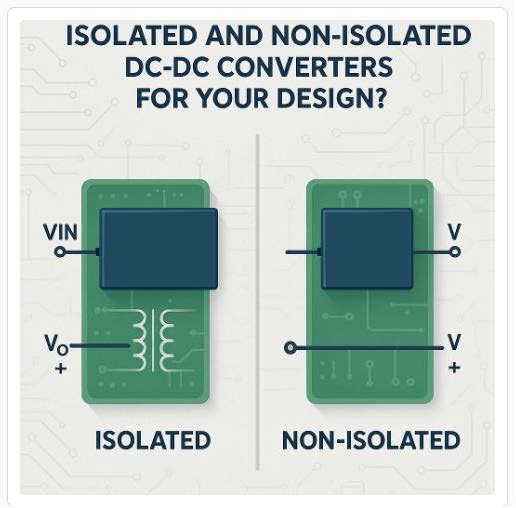
Figure 1 Isolated and Non-Isolated Diagram
This fundamental difference creates the central trade-off for the design engineer. The isolation barrier provides unparalleled safety and noise immunity but comes at the cost of increased size, weight, complexity, and price. Conversely, a non-isolated converter offers superior performance in terms of efficiency, power density, and cost, but can only be used when the system architecture does not demand isolation. The following sections will explore the engineering considerations that guide this crucial choice.
The Case for Isolation: When Safety and/or Signal Integrity are Paramount
An isolated DC-DC converter is not merely a component; it is a solution to a specific set of engineering challenges. Its selection is typically driven by stringent requirements for safety, electrical noise immunity, or functional flexibility that a non-isolated converter simply cannot meet.
The most compelling reason to select an isolated converter is for safety. In any system where the power converter is connected to a hazardous voltage, such as the AC mains or a high voltage DC bus, an isolation barrier is generally a non-negotiable requirement to protect operators, users, and downstream electronics from potentially hazardous energy levels. This barrier ensures that even if a fault occurs on the high-voltage primary side, the dangerous voltage cannot pass through to the accessible low-voltage secondary side.
This requirement is most rigorously defined in the medical industry, governed by the international standard IEC 60601-1. It is a comprehensive risk-management approach, based on the concept of Means of Protection (MOP). A MOP is a single layer of safety protection, such as specific insulation, creepage (distance along a surface), or clearance (distance through air). The standard distinguishes between the level of protection required for the equipment operator versus the patient. Protection for patients (Means of Patient Protection, or MOPP) is significantly more stringent than for operators (Means of Operator Protection, or MOOP), reflecting the patient's potential vulnerability. Meeting the highest level of patient protection (2xMOPP) requires withstanding a 4000 VAC test voltage and maintaining an 8mm creepage distance, a demanding design constraint that is placed upon the power converter’s isolation transformer and other isolation components, often necessitating the use of larger, specialized medical-grade converters.
Implementing an isolated topology introduces significant complexity. Two of the most common isolated topologies are the Flyback and the Forward converter. The Flyback, popular for lower-power applications (<150W), is simpler but uses its transformer as a coupled inductor to store and transfer energy, which requires careful magnetic design to avoid core saturation. The Forward converter is more efficient for higher power levels, using a true transformer for energy transfer, but requires additional components like an output inductor and a reset winding to prevent saturation, increasing complexity and cost. One of the biggest challenges is closing the feedback loop across the isolation barrier. This is typically done with an optocoupler, but this component's performance can vary with temperature and age, and it introduces a phase lag that can destabilize the power supply if not expertly compensated.
The control loop is not the only signal that needs to be conveyed across the isolation barrier. Design engineers also need to establish reliable and cost-effective means for transferring fault indicators such as over-voltage and over-current signals, as well as gate drive signals for secondary-side transistors. Often, when design constraints allow, these protective signals can be passed across the barrier via a magnetic field (signal transformer) or electric field (high-voltage capacitor), rather than optically. These design hurdles are a primary reason many teams opt for pre-certified off-the-shelf isolated modules.
In high-precision instrumentation, audio systems, and test and measurement equipment, electrical noise can corrupt sensitive signals and degrade performance. A common source of this noise is a ground loop, which occurs when interconnected pieces of equipment have different ground potentials, driving a noise current through the ground connection. An isolated converter is a powerful tool for breaking these ground loops. By powering a subsystem through an isolated converter, the DC ground connection between circuits is eliminated, silencing this noise source. While the transformer provides DC isolation, high-frequency noise can still couple capacitively between the windings. To combat this, high-performance converters often include an internal shield—a grounded foil layer between the windings—to intercept this noise.
While isolation can be an effective tool for combatting electrical noise, isolated topologies may also be prone to higher levels of electrical noise generation, particularly in applications with higher voltage primary circuits. The greater change in voltage across the switching elements per unit time (dV/dt) generates stronger electromagnetic fields and high-frequency current components that must be suppressed, often via the addition of shielding and both common and differential mode filtering.
In large, complex systems like industrial process controllers, it is common for different subsystems to operate with their own local ground references. Attempting to power these from a common, non-isolated source could create unintended and potentially damaging current paths. Even if two subsystems do not intentionally have localized references, in systems with high transient load currents, such as pumps and motors, these dissimilar ground potentials can be established temporarily simply by the passage of high currents through seemingly inconsequential ground path impedances. Isolated converters are essential for powering these individual subsystems, allowing each to maintain its own ground reference while receiving power from a central source.
Finally, the floating nature of an isolated converter's output offers valuable design flexibility. A key application is generating a negative output voltage from a positive input. By connecting the positive output terminal of an isolated converter to the system's primary ground, the negative output terminal will present a negative potential relative to that ground. This technique is commonly used to generate the -48V supply required in many telecommunications systems, eliminating the need for a dedicated negative-output converter. This cannot be readily achieved when the two circuits share a common reference. There are methods available for establishing negative rails in non-isolated power systems topologically (via a dedicated negative-output converter), but these methods should be deployed cautiously with special consideration to overall system impact and an analysis of current loops within the power system.
The Non-Isolated Advantage: Optimizing Performance and SWaP-C
While isolation is critical in certain scenarios, it is often an unnecessary and costly addition. In a vast range of applications, a non-isolated converter is the superior choice, offering significant advantages in performance, size, weight, power, and cost (SWaP-C).
In many modern systems, the isolation decision is made at the architectural level. A popular and highly efficient approach is the Distributed Power Architecture (DPA). In a DPA, a single, centralized AC-DC or high-power DC-DC converter provides the main safety isolation from the AC mains and generates a regulated intermediate DC bus voltage (e.g., 24V or 48V). Because this front-end converter has already provided the necessary safety isolation for the entire system, the downstream converters usually do not need to be further isolated themselves. This allows designers to use small, highly efficient, and low-cost non-isolated converters placed physically close to the components they are powering, or to establish other intermediary busses, leveraging the strengths of both converter types.
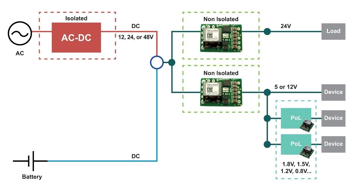
Figure 2 DPA Architecture Example
For applications where SWaP-C is the primary design driver, non-isolated converters are the clear choice. The main reason for their advantage is component elimination (BOM reduction), particularly elimination of the bulky, heavy, and expensive isolation transformer, but also a reduction in components used to transfer signals across the isolation barrier, and in the costly safety-certified front-end components, such as X and Y capacitors. Electrical spacings (creepage and clearance) required by various safety standards increase with the maximum voltage present in the design. Often, circuits that can accept a non-isolated power topology are operating at lower maximum voltages, resulting in smaller electrical spacings, and a more compact design overall. This makes non-isolated converters the default solution for battery-powered mobile devices, drones, autonomous mobile robots (AMRs), and aerospace applications where every gram and cubic centimeter counts.
Non-isolated converters also offer superior conversion efficiencies. By removing the transformer and its associated losses, efficiencies can reach as high as 97% or 98%. This hike in efficiency has impactful second-order effects. High efficiency means less energy is converted to heat within the power system, simplifying thermal management and improving system reliability. These higher efficiencies also result in extended battery life for battery-powered applications.
From a design standpoint, non-isolated topologies offer an elegant and powerful toolkit. Common topologies in this class are the Buck (step-down) and Boost (step-up) converters. For ultimate flexibility, particularly in battery-powered systems where the input voltage varies widely, the four-switch buck-boost converter is often ideal. It can seamlessly operate as a buck or boost converter as needed, ensuring a stable output voltage across the entire battery discharge cycle. However, this added flexibility does come at the cost of some additional circuit components and design complexity.
These flexibilities associated with non-isolated topologies extend to increased opportunities for design reuse. Many non-isolated converters are designed with very wide input and adjustable output voltage ranges. This allows a single part number to be used across multiple products or to generate various output rails, simplifying the BOM, streamlining procurement, and accelerating development. In any system where the input source and the load already share a common ground, such as most single-board and battery-powered devices, the added cost and complexity of an isolated converter provide little to no benefit, making a non-isolated topology the logical and most efficient choice.
A Framework for Decision-Making
The choice between an isolated and non-isolated DC-DC converter is a critical engineering decision that balances system-level requirements against component-level performance. There is no single "best" solution; the optimal choice is entirely dependent on the specific needs of the application. By following a structured decision-making process, engineers and technical leaders can navigate the trade-offs to arrive at the most effective and reliable power architecture.
A logical framework for this decision is as follows:
- Is Safety Isolation Mandated? If the system is powered from a hazardous voltage (e.g., AC mains) or must comply with standards like IEC 60601-1 for medical devices, then galvanic isolation is non-negotiable. At least one isolated converter is required in the system.
- If Isolation is Required, where is it Best Placed? For systems with multiple output rails, a Distributed Power Architecture (DPA) is often the superior choice. A single, centralized isolated converter can provide the primary safety barrier, creating a safe, isolated intermediate bus. This allows the use of smaller, cheaper, and more efficient non-isolated converters for the final voltage conversion steps.
- Are There Functional Needs for Isolation? If the system does not require safety isolation, consider if there are functional requirements. Is it necessary to break a ground loop to achieve high signal fidelity? Is there a need to generate an inverted voltage rail? If so, an isolated converter may be a better choice.
- If No to All of the Above, Default to Non-Isolated. If there are no mandatory safety or specific functional requirements for isolation, a non-isolated converter should be the default choice. The significant advantages they offer in terms of higher efficiency, higher power density, smaller size, lower weight, and lower cost are too compelling to ignore in a competitive market.
Ultimately, a successful power system design is one that correctly identifies and prioritizes the most critical performance parameters for the end application, making the isolation decision a strategic choice rather than just a technical one.
TDK-Lambda offers a wide range of DC-DC converters for your application, visit our website at https://www.us.lambda.tdk.com/resources/catalogs/board_mounted_brochure/