TDK-Lambda Americas Blog
What external components are required for a DC-DC converter?
Thursday, January 2, 2025
Introduction
Using an off the shelf DC-DC converter for a new design reduces development time and risk. A discrete solution can potentially save money if the production volumes are very high, but there may be additional costs associated with having magnetic components built. For example, safety certification may be required if isolation between the input and output is required or EMI and immunity standards need to be met.
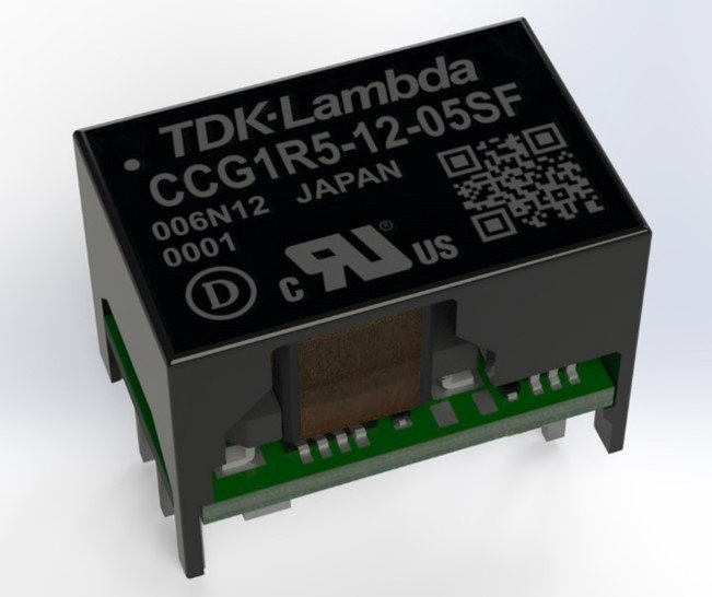
Figure 1: TDK-Lambda’s CCG 1.5 & 3W DC-DC converter
Block diagram
Figure 2 shows the block diagram for the CCG 1.5 -10W models
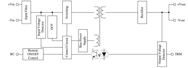
The input voltage is applied to +Vin and -Vin. A small internal filter circuit reduces externally and internally generated noise. The Input Voltage Detector ensures there is sufficient voltage to operate, the OCP protects the converter against an over current condition. The RC terminal allows the DC-DC converter to be turned on or off, reducing standby power consumption or to enable or activate the output voltage.
The Control Circuit (supplied by the bias power supply) manages the Switching circuit and Rectifier to provide a regulated output voltage.
Input to output isolation is provided by the transformer and secondary signals via the opto-coupler from the output voltage detector and output adjustment terminal (TRM) for setting or adjusting the output voltage level.
External components
Input fuse (F1) and the input capacitor (C1)
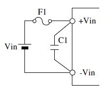
The majority of DC-DC converters do not have an internal fuse to accommodate +24 & -48V input systems. If the input voltage -Vin is connected to ground, the fuse should be connected to +Vin. If the V+ input is connected to ground (for a -48V system), then the fuse should be in-line with the -Vin terminal.
The manufacturer’s instruction manual should state the type of fuse that is required and the current rating. For the 1.5W rated CCG, the recommended series is the DC86V11CT series manufactured by SOC. This is a UL rated fuse that can withstand an inrush current surge.
Depending upon the circuit, capacitor C1 may or may not be required. If the input wiring is long or has a filter inductor in series with the input source, then a capacitor may be required to maintain stability. This reduces ripple on the input or decreases the conducted emissions. C1 should be positioned as close to the input terminals of the converter as possible to reduce wiring and pcb track impedance.
Output capacitor (Figure 3)
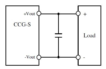
Figure 3: Output capacitor
The use of an output capacitor is optional. Adding capacitance across the output will reduce the output ripple and decrease output fluctuations due to pulse loading or sudden changes in the output load.
When voltage is initially applied to an external electrolytic capacitor it may draw a pulse current. Too large a capacitance value may trigger the overcurrent circuit causing the converter to shut down. The manufacturer’s installation instructions should give guidance as to the maximum value.
Reverse input protection
Accidental reversal of the input voltage polarity will cause damage to the DC-DC converter. Two methods are suggested.
Figure 4 has the reverse polarity diode across the input terminals of the converter. In the event that the input voltage polarity is reversed, the protection diode will conduct causing the fuse F1 to blow. Under correct conditions, the diode will not conduct and no power losses will occur. Select a diode with a higher voltage rating than the input voltage and a higher surge rating than the input fuse.
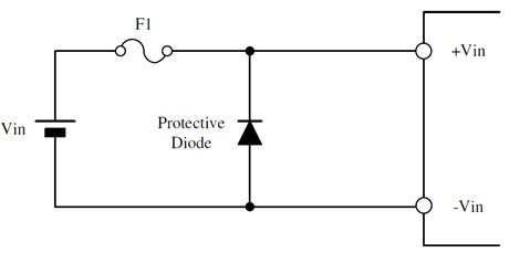
Figure 4: Diode fitted across the input terminals
Figure 5 shows the reverse protection diode in series with the fuse. If the input voltage is reversed, the diode will block any input current and the fuse will not blow. The disadvantage to this method is that during normal operation the diode will dissipate power continuously. If the power source is a battery, more frequent charging will be required. Again select a diode with a higher voltage rating then the input voltage and a higher surge ratting than the input fuse.
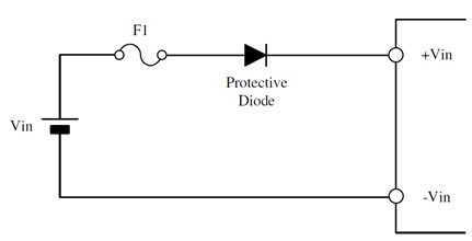
Figure 5: diode connected in series with the input terminal
Protection against instantaneous input voltage drop
If the DC-DC converter shares the input source with other devices, it may be subjected to an instantaneous drop in voltage. This could be from the start-up of a thermally controlled DC fan for example and may cause instability on the output.
Figure 6 is similar to figure 5 with the input capacitor C1 fitted. In the event of a drop in the input voltage, the DC-DC converter draws energy from C1. It is sometimes referred to as a “hold-up” circuit.
This circuit can also help mitigate voltage surges when the input voltage is suddenly disconnected by a switch over long input cable lengths.
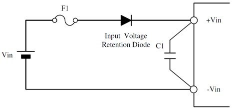
Figure 6: Capacitor hold-up configuration
Output voltage adjustment
On CCG single output models, the output voltage can be adjusted within a limited range. Figure 7 shows the trim resistor Rb connected between the TRM terminal and -Vout to increase the output voltage. To reduce the output voltage, Rb is connected between TRM and +Vout. Figure 8 shows how to use a potentiometer for variable adjustment. Ensure that the DC-DC converter is not adjusted beyond the product rating.
Keep the distances between the converter and resistors as short as possible to avoid electrical noise from affecting the output voltage.
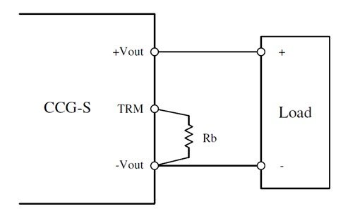
Figure 7: Using the trim pin for increasing the output voltage
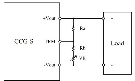
Figure 8: Using a potentiometer for adjustment
Remote On/Off
Turning the output voltage on or off can put a DC-DC converter into standby for energy saving, or to facilitate voltage sequencing of multiple converters. The Remote Control (RC) terminal can be used for this.
Figure 9 (left) shows how to use a transistor or relay connected on the primary side (referenced to the input).
For control using an external circuit on the secondary side (referenced to the output), see Figure 9 (right) an isolated opto-coupler can be used.
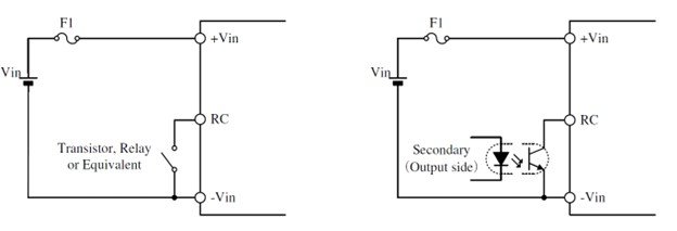
Figure 9: Using the remote on/off function
An evaluation board is available for the CCG 15W and 30W converters which can give further information on component selection and printed circuit board layout.
Please do not hesitate to call or email TDK-Lambda Americas Technical Support or your local sales office if you have any questions regarding a power supply for your next project. https://www.us.lambda.tdk.com/contact/.