TDK-Lambda Americas Blog
Tips for using the PFH500F AC-DC power module
Thursday, January 4, 2024
Introduction
Power modules are an ideal way of developing custom, low profile, fan-less, conduction cooled AC-DC power supplies. Applications include LED advertising displays and sealed enclosures for outdoor and harsh environments.
The PFH500F AC-DC power modules are TDK-Lambda’s next generation of AC-DC isolated power supplies. Like any mid-wattage power module, the PFH requires external components and cannot be used without them. This blog will discuss how the PFH500F operates, plus tips on how to select the right components and design the printed circuit board.
The TDK Product Center website has some good information on these modules, including the available evaluation kits, evaluation and immunity data, as well as the specification and instruction manual.
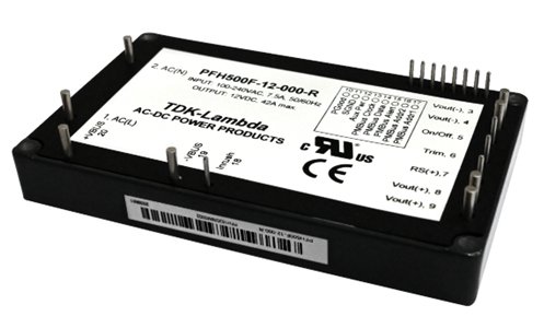
Figure 1: TDK-Lambda PFH500 AC-DC power module
If you are considering using the PFH500F it is strongly recommended to obtain an evaluation kit for initial testing. For less than $600 from our distribution partners it comes fully assembled, with the power module and a heatsink fitted, ready to power up. It will save you a lot of time!
Block diagram
First, a high-level explanation of how the module works, using the block diagram in Figure 2. Note that the blocks highlighted in red indicate that external components are required for operation.
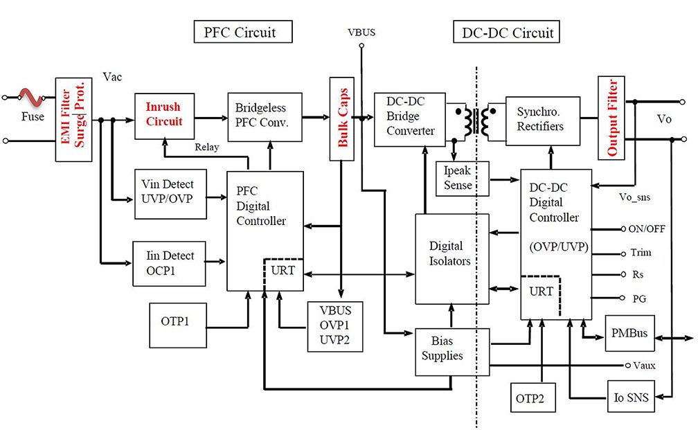
Figure 2: PFH500F block diagram
The AC source is fed through the inrush circuit, which reduces the peak input current upon start-up, and into the bridgeless power factor correction (PFC) switching circuit (operating at a fixed frequency of 145kHz). This converts the AC into a high voltage DC around 385V. The external “bulk” hold-up electrolytic capacitor(s) are used to store energy and keep the converter operating during brief interruptions to the AC supply.
The DC-DC converter circuit converts the high voltage DC into an isolated low voltage DC for the output, using high efficiency synchronous rectifiers. Externally mounted electrolytic and ceramic capacitors filter the output voltage to reduce ripple and noise.
Both the PFC and DC-DC bridge converters are controlled digitally, via digital isolators, monitoring the voltage, current and temperature against under-voltage, over-voltage, over-current and over-temperature conditions. The DC-DC digital controller also provides the PMBus interface, traditional signal functions, output adjustment, current sharing and remote on/off. A loosely regulated, isolated 12V 0.2A bias supply can be used to drive external customer developed circuits.
External components
Figure 3 is an extract from the instruction manual showing the external components that are necessary for the power supply to operate and meet the EMI and immunity standards. We will review each portion individually in more detail.
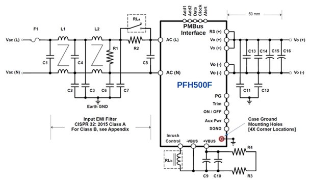
Figure 3: PFH500F external components
Input filter section (Figure 4)
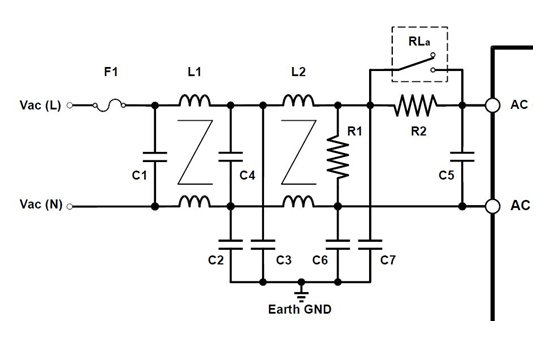
Figure 4: Input filter section
In many countries it is necessary to ensure that your end product meets the applicable EMC standards and is required for the application of the CE and UKCA marks. In the PFH500F evaluation reports, the product was tested to EN55032 Class B. An external two-stage filter circuit (shown in figure 4) is suggested for the best performance.
Fuse F1 should be a safety certified 10A 250V rated fast-blow type. If modules are being used in parallel, each module should have its own fuse and EMI filter.
Polypropylene capacitors C1 (1uF), C4 (1uF) and C5 (2.2uF) are connected across Line and Neutral and avoid electrical noise from travelling back into the AC source, keeping it localized in the power supply. These must be safety certified “X” film capacitors with a recommended 305V rating. Position C5 close to the AC(L) and AC(N) of the power module for maximum effectiveness.
Capacitors C2, C3 (3300pF), C6 and C7 (470pF) also avoid electrical noise from going back into the AC source. This noise current is bypassed into the earth ground. As they are connected between Line / Neutral and ground, these must be safety certified “Y” capacitors. Connect C6 as close as possible to AC(L) terminal of the PFH500F and C7 as close as possible to AC(N) terminal for maximum effectiveness.
The common mode chokes L1 and L2 should have a minimum value of 6.3mH and have a current rating of 10A. TDK-Lambda Part #: ARA00499 was used during TDK-Lambda’s testing process.
Bleed resistor R1 discharges the X capacitors to avoid an electric shock when unplugging the AC power cord. The value should be 470kΩ and rated at 2W. Now that IEC 62368-1 is in force, the resistor should comply with the standard, or two resistors should be used in parallel to pass the “single fault clause”.
The inrush current that occurs when the AC is applied is limited to a pre-determined level by resistor R2 (22Ω). It is strongly recommended that a ceramic wire wound, thermal fused resistor is used. TDK-Lambda’s part number is AR00719.
Once the initial inrush current has charged up the bulk capacitance, the PFH500F module will energize the relay coil. The relay contact will then short out the inrush resistor R2, to improve the operating efficiency.
Bulk capacitors and relay control (Figure 5)
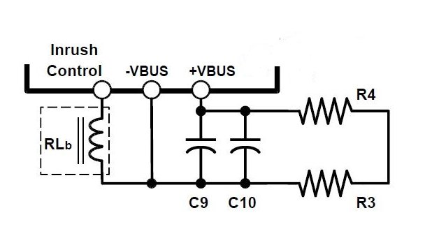
Figure 5: Bulk capacitors and relay control section
The relay RL must have a minimum 10A / 277Vac rating, and a 12V / (15 to 20mA) nominal coil operating voltage and current is recommended. A Panasonic JVN1A-12V-F relay was used during the testing process.
As previously mentioned, the bulk electrolytic capacitors C9 (470μF, 450V) and C10 store energy to allow the power supply to operate through brief interruptions in the AC voltage. Use 105ºC rated parts for a longer operating life. The instruction manual provides additional details.
Resistors R3 (470kΩ / 2W) and R4 discharge the bulk capacitors to a safe voltage after the AC power is removed.
Output filtering and signals (Figure 6)
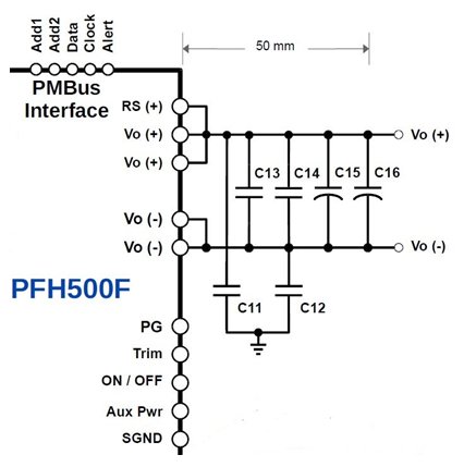
Figure 6: Output filtering and signals section
In Figure 6, the positive remote sense is shown as connected locally. To compensate for small wiring and cable drops this would be connected to the load.
C13 (10μF), C14, C15 and C16 are ceramic capacitors, chosen for lower ESR and greater operating life that electrolytic capacitors.
C11 (470pF) and C12 are also ceramic or film capacitors and reduce high frequency noise on the output. These should be Y2 as high test voltages are often applied across these capacitors (between the output terminals and the module metal case) during the output to ground hipot (1.5kVdc). These should be connected as close as possible to the Vo(+) and Vo(-) terminals for maximum effectiveness.
There are four mounting locations on the PFH500F module, one at each corner of the module. These are either threaded or non-threaded depending on the option code. These points can be connected to earth ground.
SGND and Vo(-) are considered to be two separate grounds inside the PFH Series module. They should not be connected together at any point. Vo (-) is used as the return path for output load current and voltage, while SGND is used as the return path for logic signals. These include the PMBus connection, Power Good, Trim, ON / OFF, and the 12V Aux bias power supply.
The output voltage can be adjusted using a trim resistor (see datasheet and the instruction manual for calculations).
Printed circuit board
The printed circuit board design should be completed with input from the person who handles your certification with the regulatory safety bodies (UL, CSA, etc). Minimum spacings (creepage and clearance) are required between high voltage copper traces and between primary and earth.
A multiple layer circuit board is recommended with a ground plane to reduce EMI. The higher current carrying traces should be thick and positioned close together to reduce the impedance for the capacitor switching currents. The thickness and mounting hardware of the circuit board should reflect the weight of the components.
The PFH500F evaluation instruction manual contains board files which can be used as a reference.
Do not hesitate to call or email TDK-Lambda Americas Technical Support or your local sales office. https://www.us.lambda.tdk.com/contact/