TDK-Lambda Americas Blog
How does a power supply output overvoltage protection work?
Wednesday, October 25, 2023
Introduction
Most AC-DC power supplies and isolated DC-DC converters will have an Over Voltage Protection (OVP) circuit, which will protect the load in the event of an internal failure. Without it, the load could be severely damaged, a fire may occur or a potentially high voltage could cause an operator to receive an electric shock. Not all overvoltage protection circuits operate in the same manner and this blog will discuss how most operate and why.
What may cause an OVP condition?
Incorrect output voltage or OVP setting adjustment
Probably the most common cause of an overvoltage condition is an operator adjusting the power supply output voltage too high. The remedy is to switch it off, turn the output adjustment potentiometer counter clockwise and re-apply the input power. If the power supply has an adjustable OVP potentiometer, refer to the instruction manual for adjustment details.
Incorrect system wiring
Wiring is a frequent reason for an OVP condition. The remote sense function is used to compensate for voltage drops in the wiring from the power supply terminals to load (Figure 1).
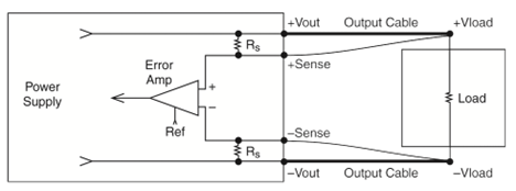
Figure 1: Remote Sensing
The remote sense allows the voltage regulation at the load where the remote sense leads are connected, and the control circuit either raises or lowers the output accordingly. If the output voltage is factory set to 24V for example, and the total cable voltage drop is 2V, the control circuit will adjust the power supply output voltage terminals to 26V.
If the remote sense connections are reversed, the control circuit will try to raise output voltage higher than the negative voltage it is sensing and trigger the OVP.
Output cables that are too long, or are not adequately sized will cause the power supply to try and compensate. If the power supply output voltage is 5V and the OVP setting is 6.5V, then a total cable drop of 1.8V will cause the OVP to activate. More on remote sensing can be found in our April 2013 blog.
Voltage spikes or surges on the output
If the power supply is driving relays, solenoids or DC motors, voltage spikes may be transmitted back to the output terminals. This may cause the OVP to trigger.
There is a different blog showing how to address this with external diodes on our blog site.
How OVP circuits operate
There are two commonly used methods depending on the product’s rated power, price sensitivity and application.
Zener diode clamp (non-resettable)
For some low wattage, low cost supplies, usually less than 30W, a simple Zener diode clamp may be used. Figure 2.
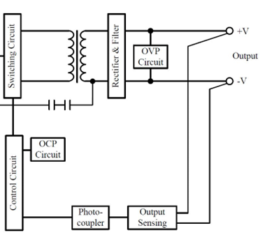
Figure 2: Zener clamp OVP
If an internal failure in the power supply control circuit causes the output voltage to rise, the Zener diode will conduct. This would result in the diode over dissipating, creating a short circuit. The power supply current limit would then activate, usually in shutdown mode, turning the power supply off and protecting the load. Replacement of the power supply would be required as the repair of a low cost product would normally not be cost effective.
Note that most low wattage power supplies do not have or need remote sense due to their low output current.
Resettable OVP
Figure 3 shows the relevant sections of a power supply with a resettable OVP. Photo-couplers (or opto-couplers as they are also called) are used to feedback signals across the primary/secondary safety barrier. The Output Sensing coupler is used to provide feedback on the output voltage status to the Control Circuit. The OVP Sensing coupler will provide a signal to the Control Circuit if the output voltage is too high and initiate an output voltage shutdown.
Provided the overvoltage condition is generated by an external source like a voltage spike (and not an internal product failure) the power supply can be reset with no damage.
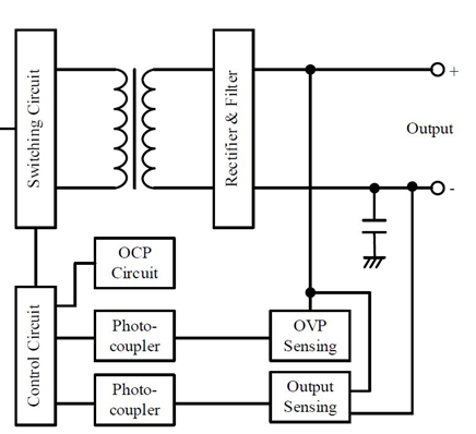
Figure 3: Power supply block diagram with a resettable OVP
Types of resettable OVP circuits
OVP shutdown requiring manual intervention
For many AC-DC power supplies, some form of manual interaction is required to reset the overvoltage protection circuit. This can be in the form of removing the AC power for a short period of time, or activating the remote on/off function.
After disconnecting the AC, it is important to wait a few minutes for the capacitors inside of the power supply to discharge. Products like the 1500W rated CUS1500M (Figure 4) have large amount of bulk capacitance to “hold-up” the output voltage during AC interruptions. After the unit has shutdown due to the OVP triggering, the power supply will of course have zero load and those capacitors will discharge slowly – so be patient!
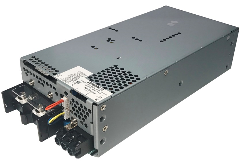
Figure 4: TDK-Lambda CUS1500M 1500W medical AC-DC power supply
Auto resetting OVP
In applications where the power supply or DC-DC converter is in a remote location and not easily accessible, an auto resetting OVP may be considered. In the event that a voltage spike occurs, the power supply will shutdown momentarily and then try to restart. The CN-B110 DC-DC 200-300W converters are designed for electric railroad applications powered by either an overhead gantry or “third rail”. Sending out a technician to manually reset equipment on a high speed train would be somewhat difficult! By default, the CN-B automatically restarts after an OVP condition and if required, a latching option can be specified in the model number.
This type of OVP is getting less common now as many AC-DC products have some form of digital interface that can be programmed to restart.
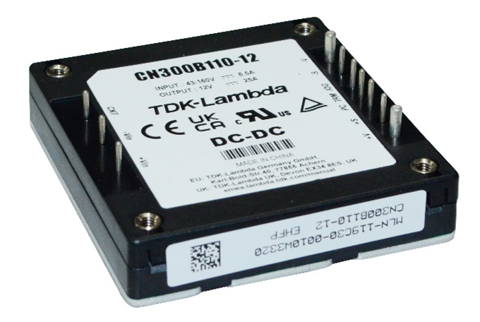
Figure 5: CN-B 200-300W DC-DC railroad converters
Protection by duty cycle limiting
TDK-Lambda’s GQA and HQA industrial DC-DC converters (Figure 6) have a maximum duty cycle limit to help reduce the risk of over voltage appearing at the output of the power module during fault conditions. If there is a fault in the voltage regulation loop, the protection circuitry will cause the power module to limit the output voltage. When the condition causing the over-voltage is corrected, the module will operate normally.
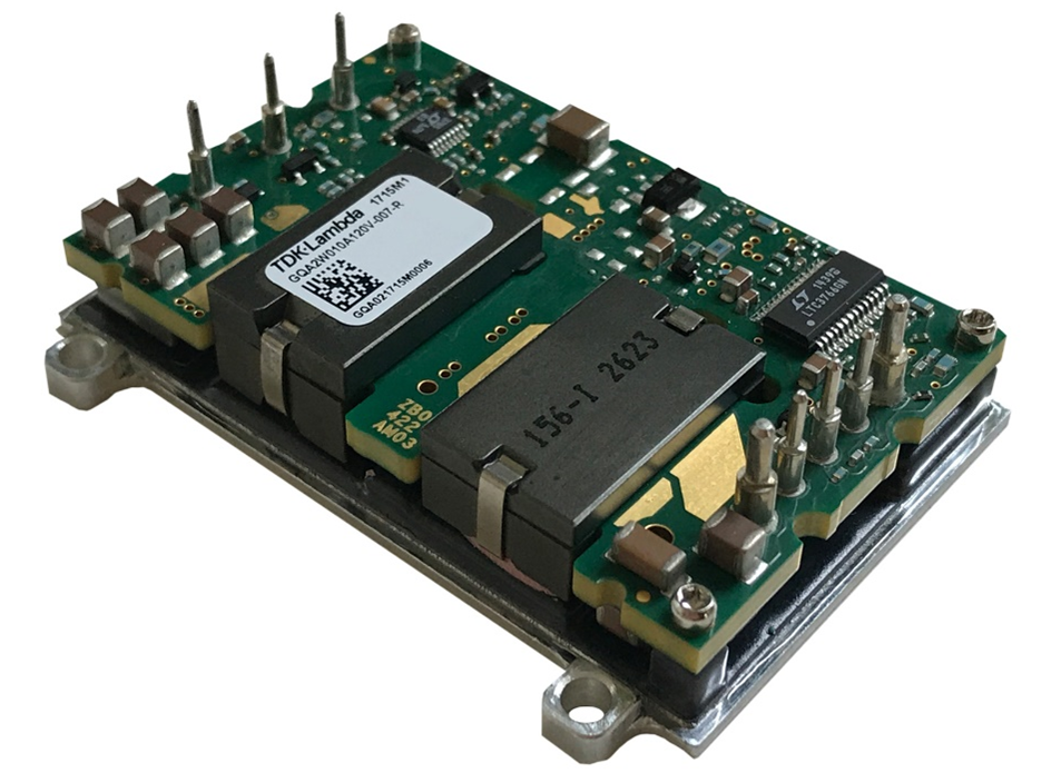
Figure 6: GQA 120W DC-DC converter
Tracking OVP
Power supplies with a wide output adjustment range require tracking overvoltage protection. Rather than having a fixed over voltage point, these provide an OVP that automatically adjusts to a percentage of the output voltage. The TPS4000 power supply’s overvoltage is set at 110 – 135% of the output voltage set point. For example, if the product’s output voltage range is 19 to 28V, the OVP will automatically protect a load requiring 20V against voltages greater than 24V. A non-tracking OVP would be set in excess of the maximum adjustment range and could be as high as 34V, potentially damaging the load.
PMBus™ interfaces
Power supplies fitted with a digital interface often have the capability to set the overvoltage set point electronically. The PFH500F AC-DC 500W power modules (Figure 7) have a PMBus™ interface and the capability to write an OVP value into its memory that best suits the application or load.
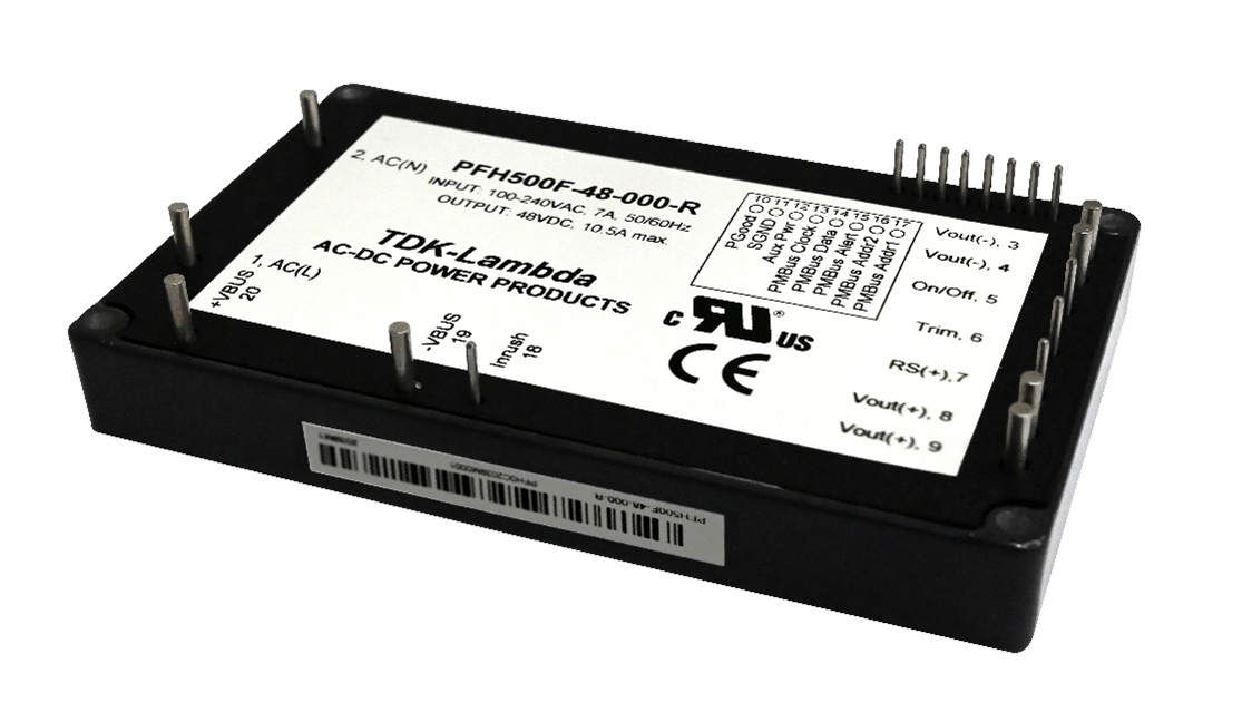
Figure 7: PFH500F AC-DC power module
The GENESYS+™ series of programmable power supplies also has the capability to adjust the OVP set point via software or using the front panel controls.
Summary
This article is another example of why you should involve a power supply manufacturer at an early stage in your design. There is, of course, no charge to talk to their field application engineers or technical support staff. It may give you insights into technology or products that will make your job easier and potentially avoid issues later!
Power Guy