Tuesday, September 27, 2022
Background
PMBus® is a power management bus for the digital management of power supplies, not to be confused with digital control used in power supplies. Since 2005 the specification has provided a standardized low-cost,, flexible and simple to use way of communicating with AC-DC power supplies and DC-DC converters. The bus is based on the I2C protocol and is a variant of the System Management Bus (SMBus). Currently around 50 companies are members of the PMBus organization and to find out more you can visit their website https://pmbus.org/. TDK-Lambda has been an “adopter” member since 2010.
Why was it developed?
The data center industry sparked a need for a common communication method between power devices. The large amount of power being consumed made efficiency improvements a high priority. ASIC companies were developing efficient, fast products that required multiple voltage rails with the ability to adjust those voltages. System designers were moving towards Distributed Power Architectures (Figure 1) and non-isolated POL (Point of Load) DC-DC converters to handle the fast di/dt changes.
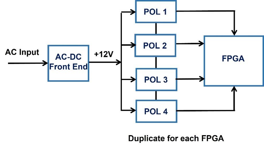
Figure 1: Distributed Power Architecture
To lower power consumption, adaptive or dynamic voltage scaling is required to adjust the output voltage of the PoL or AC front end according to each processor’s loading. The PMBus provides communication within the system to do this.
The PMBus can also be used to control the “front end” hot swap AC-DC power supplies according to the overall system requirements. For example, if the system load is 7,500W, four 2,500W power supplies with current share may be configured to provide 3+1 redundancy. Each power supply would normally provide 1,875W (75% load, 92.7% efficient). If one fails, the other three will automatically increase their outputs to 2,500W until the failed product can be replaced (Figure 2).
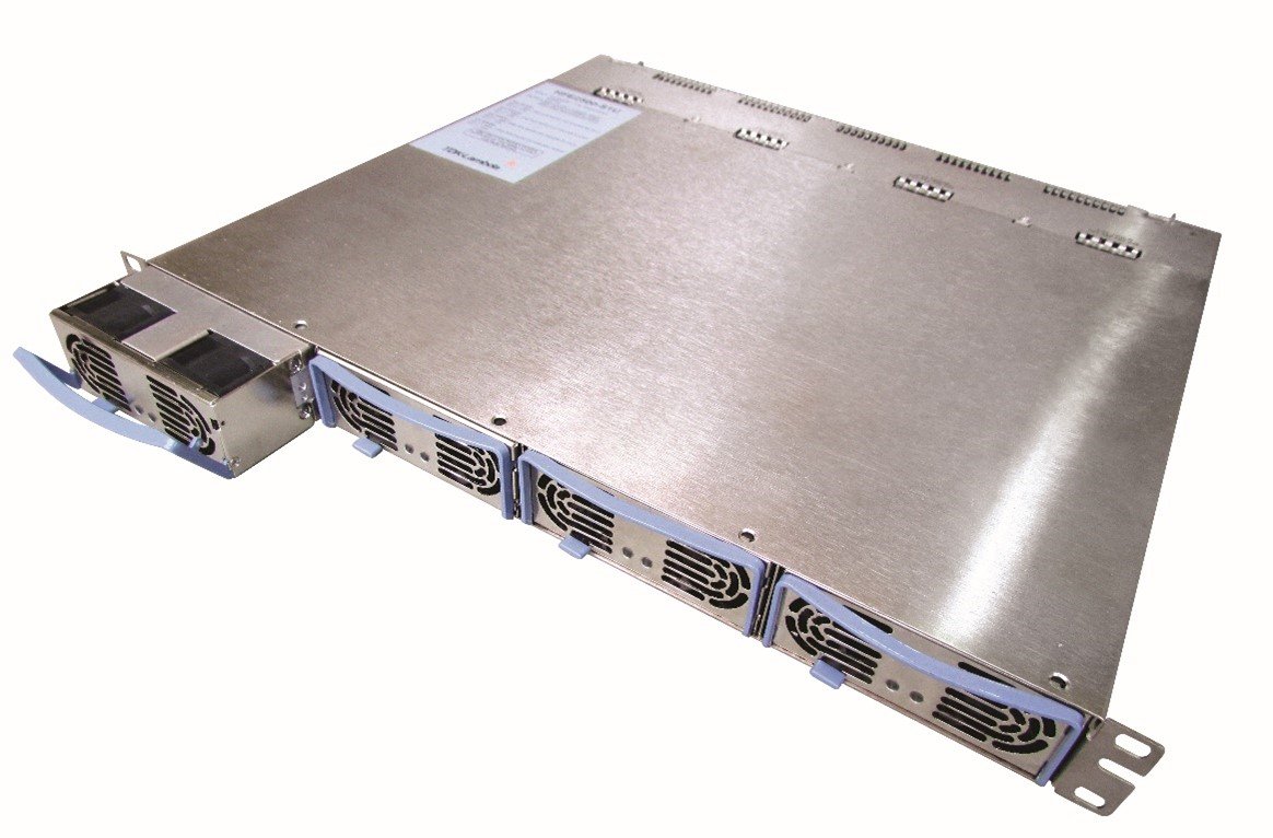
Figure 2: TDK-Lambda HFE 2500W power supplies in a 19” rack mounted shelf
During off-peak data center usage, the system load might decrease to 5,000W equating to 1,250W (50% load, 92% efficient) for each unit. As power supply efficiency reduces at light loading (Figure 3), one power supply can be inhibited so the other three will provide 1,666W (66.6% load, 92.7% efficient). This allows them to operate at their peak efficiency, reducing their power loss. Redundancy is still maintained as two power supplies can still provide 5,000W. The PMBus would get notified if a failure occurs and activate the inhibited unit. These incremental power savings may seem small, even factoring in reductions in air conditioning, but in 2014, data centers accounted for about 2% of the total US electricity usage.
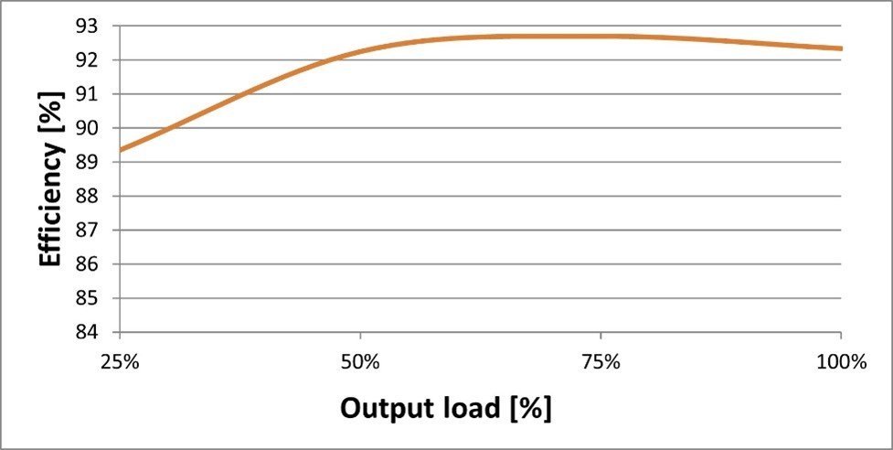
Figure 3: power supply efficiency versus load
Other benefits of using the PMBus are data collection, live performance monitoring, assisting test and qualification (voltage margining of outputs), failure analysis and preventive maintenance.
Even if your power supply application does not use kilowatts of power, there are additional benefits to using the PMBus just for the data it can provide.
Monitoring
Some power supplies have an “output good” open collector signal. Instead, the PMBus can digitally provide you the output voltage, plus the output current and temperature. If the temperature is rising it could be blocked vents or fans failing.
Output voltage and current limit programming
If you are adjusting the power supplies output voltage or current limit set point manually, this could be set digitally using the PMBus.
Using the remote on/off function
Rather than using a relay, the power supply output voltage can be inhibited or enabled using a command in the system software.
Manufacturing data
The serial number and manufacturing date can be read from the PMBus and stored digitally.
Alarm fault or warning functions
The power supply fault data, fan fail, AC fail or output fail signals can be used to assist remote fault finding for repair of maintenance purposes.
To summarize, using a PMBus interface can provide you with additional features and ease the integration of fault-finding information into your system. Many customers create their own GUI (Graphical User Interface) which can be pulled up as a menu item on their equipment’s monitor or display. This may allow a maintenance person to identify what parts are needed to repair a system before visiting the facility where their equipment is installed.
Most power supply companies will have locally based Technical Support trained to answer any programming questions.
Power Guy