Friday, May 27, 2022
As power supplies are not 100% efficient, they have internal energy losses resulting in an increase in component temperatures. Manufacturers can thermally manage this by using metal heat sinks for power devices or by placing surface mount power components on a multi-layer pcb for conduction cooling. Heat sensitive components, like electrolytic capacitors, are positioned physically apart from hot components, like transformers and inductors, which may operate at a higher temperature.
Some power supply manufacturers have a better design than others. I remember when engineer friends contacted me after we launched the 150W CUS150M 2”x4” power supply . They wanted to know where the heatsinks were (Figure 1) and what the final product would look like with them fitted! The power semiconductors are surface-mounted on the underside, allowing additional component spacing for cooling.
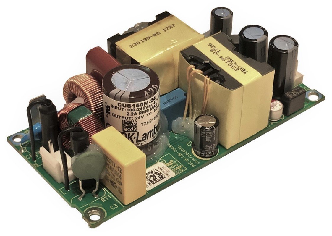
Figure 1: CUS150M power supply
We have several articles posted on how higher temperatures decrease electrolytic capacitor life. Basically each 10°C rise in the capacitor’s temperature will halve its operating life. Even semiconductors deteriorate over time, with higher operating temperatures , their life is shortened considerably.
Derating curves are often provided by manufacturers to ensure the product provides an acceptable field life. There are often several different derating factors to be considered.
Temperature derating is the most common. A chart is provided showing the maximum safe power level that can be drawn by the load. Figure 2 shows the power supply can provide full power up to 50oC ambient with a linear derating of 50% power at 70oC.
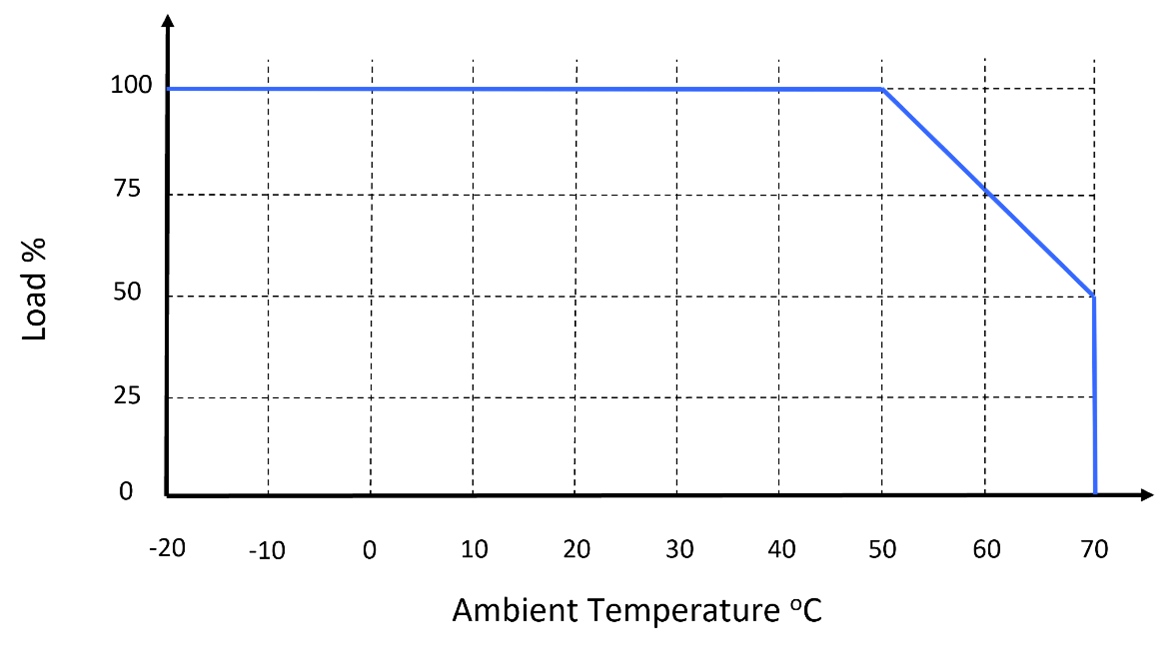
Figure 2: Derating graph of load vs. ambient temperature
The mounting orientation can affect convection cooled supplies as heat will rise. According to the installation manual of the TDK-Lambda RWS150B, the most effective mounting orientation is (A) - on its side. Note that mounting (E) is not possible as heat would be trapped inside the case, potentially leading to overheating and thus reducing its field life. These charts are referred to in the safety certification reports.
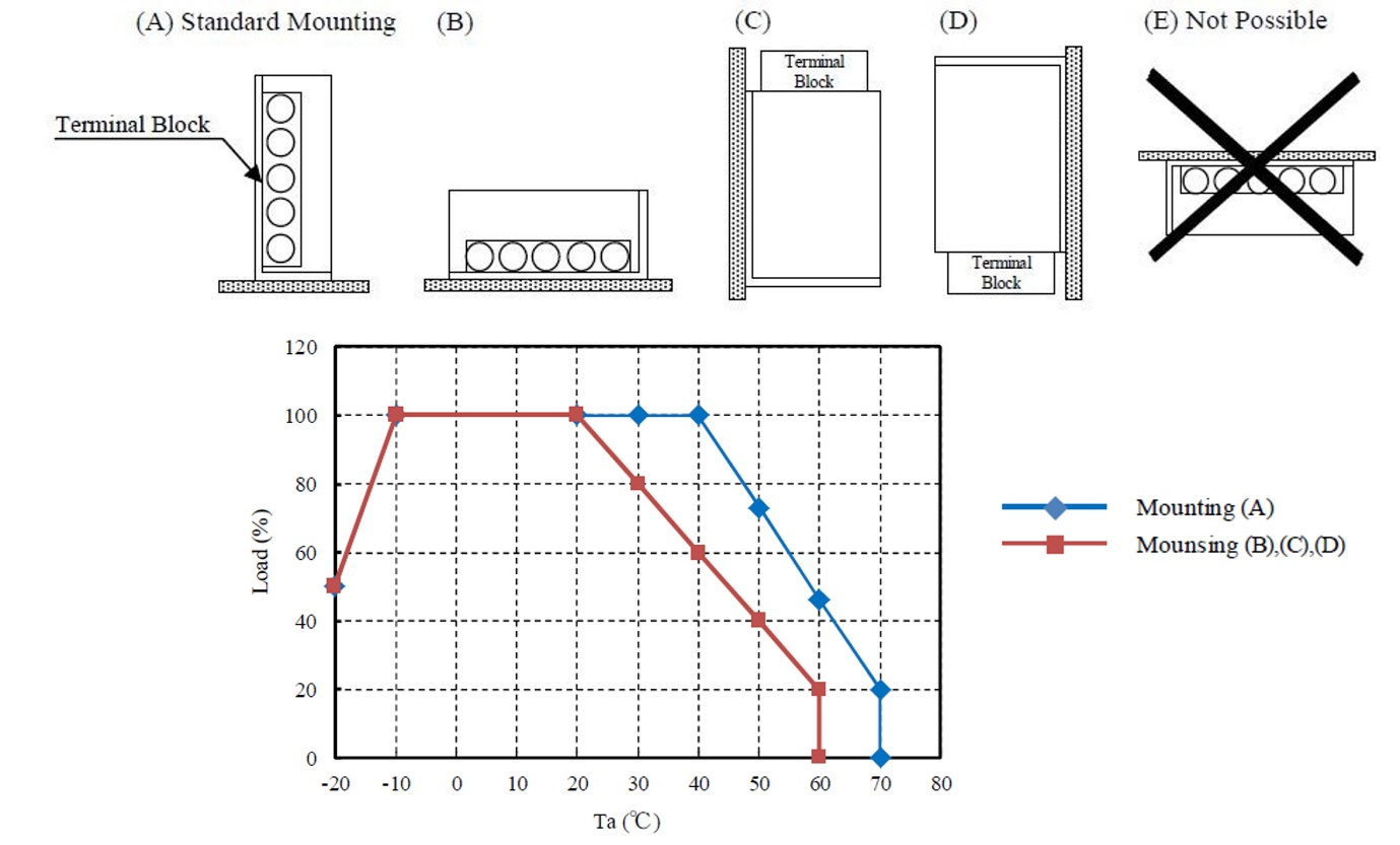
Figure 3: RWS150B orientation and derating charts
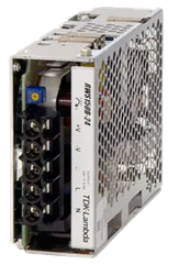
Figure 4: RWS150B power supply
Mounting direction (A) allows some conduction of the case (where the power semiconductors are secured) to the system chassis. More importantly it allows air to enter through the case ventilation holes and exit through the “top”. Figure 4.
Low temperature derating can be seen in Figure 3 also, showing 50% power at -20oC. As expected, this has nothing to do with overheating, but with cold temperature start-up. At 50% power the RWS-B will have a smooth output start-up characteristic without repeated attempts to start up. See this blog for more information on the subject. Once the unit has warmed up full power can be drawn.
Input derating may also be stipulated, particularly with AC-DC power supplies with an 85Vac to 264Vac input. This affects the input filter and rectification (bridge) circuitry (Figure 5).
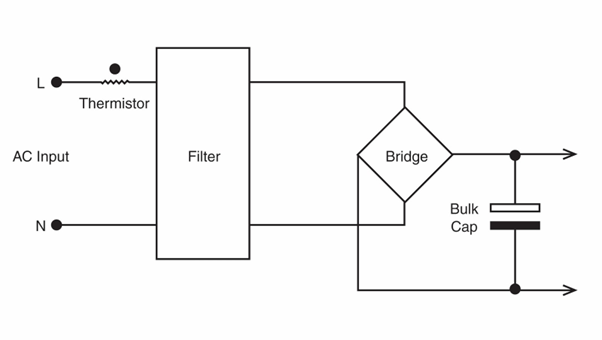
Figure 5: Input section
When the input voltage is 85Vac, more current is drawn from the AC. The EMI filter and the diodes in the bridge will run hotter unless the load current is reduced by derating (Figure 6).
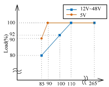
Figure 6: RWS150B input derating chart
The 5V output model has an additional 10% power derating due to its lower 77% efficiency, compared to the 12V-48V models which average 85%. The higher the output voltage, the higher the efficiency, the less input current is drawn.
Cooling of the power supply can also impact the amount of power the power supply can provide. Open frame products are often provided with conduction and external forced air ratings (Figure 7). Passing air over or through a unit will generally allow more power to be drawn.
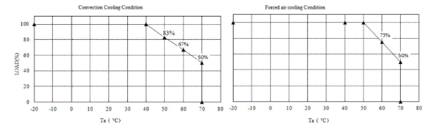
Figure 7: Convection and forced air ratings
The amount of airflow and ensuring the air is going across the power supply in the right direction is important. Some manufacturers show the optimum forced cooling direction to ensure the maximum possible power is available. Be careful that other items in your system do not restrict the airflow, as they may severely impact reliability.
One final, important point! These derating percentages are cumulative. For example, if the output power at 85Vac input is derated to 90% and the allowed power is 50% at 70oC ambient, then the maximum output power will be power derated by 0.9 x 0.5. A 150W rated power supply will be rated at a maximum of 67.5W. If this is insufficient for your needs, then consider a 200W or even a 300W model. Operating a supply at its maximum power rating is never recommended.
The best way of determining if the airflow is sufficient is to measure key component temperatures. The Power Guy video explains why you should thermocouple a power supply.