TDK-Lambda Americas Blog
Using Droop Mode Current Share Power Supplies
Parallel Operation
DIN Rail
Application Information
DRF
July 29, 2015
Connecting power supplies in parallel is commonly used to increase the available output power or to provide system redundancy in the event of a power supply failure. The correct and reliable way to connect two or more power supplies in parallel is to have them equally share the load current.
If “brute force” current share is used (connecting power supplies in parallel without regard to load sharing), it can lead to one or more of the units operating in overload and a reduced field life due to overheating. Refer to my earlier blog article.
There are two main (analog) techniques for getting power supplies to share the load - “active” and “droop” mode.
Active current share uses a signal wire interlinking two or more power supplies. Simply put, the voltage on the wire is proportional to the total current supplied to the load. That voltage is used to “inform” a unit that it is not contributing enough current, thus raising its output voltage to produce more current. In telecom and datacom systems, the power supplies are usually rack mounted and plugged into a pcb backplane. The current share connection is therefore identical from installation to installation.
On the other hand, industrial applications tend to use hard-wired DIN rail mount power supplies. The cable routing can change dramatically between installations. Cable lengths can be quite long causing the current share signal connection to be vulnerable to EMC interference from motors and relay switching. One solution that does not need any current share connection is droop mode.
Droop mode is a very simple way of paralleling power supplies. The output voltage drops (droops) in proportion to the current drawn from the power supply. If one power supply is supplying more current than the others, the output voltage will fall, and load balancing will occur. Certain electronic loads can be sensitive to variations in the supplied voltage (for example, 3.3V or 5V for logic ICs), but typically 12V, 24V or 48V outputs drive relays, DC-DC converters or motors are more tolerant to droop mode current share.
Very often this feature is standard on DIN rail power supplies 100W and above and is enabled by either a switch, or the removal of a wire link or jumper on a connector (see TDK-Lambda’s DRF series shown below).
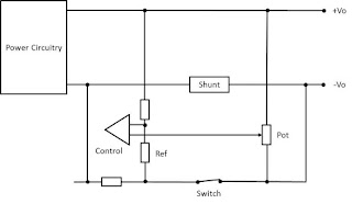
When the DIN rail power supply is not operating in parallel, the switch is closed (or wire link kept in place). The internal control circuit will compare the output voltage to a reference (Figure 1). Any change in the output voltage due to load will be compensated for, and the output regulation will be minimal – in the order of 10mV.
When two or more power supplies are connected in parallel, the switches (or links) are opened (Figure 2).
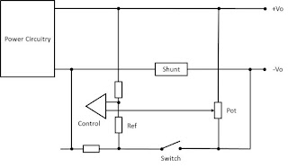
As the output current increases, the voltage across the shunt will add to the voltage across the output, causing the control circuit to compensate and lower the power supply’s output voltage.
As an example, for TDK-Lambda's 24V 10A DRF240-24-1 power supply, the droop characteristic is at 64mV / A. Table 1 shows the output change against load when droop mode current share is enabled.
| Output Voltage | Output Current |
| 24.00V | 0A |
| 23.84V | 2.5A |
| 23.68V | 5A |
| 23.52V | 7.50A |
| 23.36V | 10A |
Table 1
When using power supplies in droop mode current share, care must be taken to:
1. Set the output voltages of the power supplies to the same voltage. The output voltage can be adjusted slightly higher if needed, to offset for the droop voltage.*
2. Use the same length and same gauge of wire from the output to the load for each unit.
3. Note any additional de-rating stated by the manufacturer. This avoids tolerances from overloading a unit.
4. Do not exceed the manufacturer’s recommendation for the number of power supplies that can be paralleled.
5. Make sure the parallel switch is in the right position, or the wire link is removed!
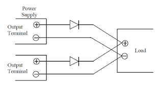
* If the power supplies are being used in redundant mode with ORing diodes, set the output voltages higher to compensate for the forward voltage drop (Vf) of the diode. The function of these diodes is to prevent the bus voltage from being pulled down due to an internal short in a faulty power supply. The diodes should be rated to carry the full output current of the power supply.